


| 상품명 | Arduino M0 Pro (Zero Pro)/이태리 정품/Cortex-M0/32-Bit ARM/디버거(EDBG)가 보드에 탑재 |
|---|---|
| 상품요약정보 | Arduino Uno 의 32-Biit 확장판, Atmel의 Cortex-M0 ARM코어 ATSAMD21 MCU 기반, 향상된 플래쉬 와 램 메모리의 빠른 성능으로 8-Biit 에서 할수 없었던 보다 많은 프로젝트 진행가능, Atmel 임베디드 디버거(EDBG)가 보드에 탑재 |
| 판매가 | 67,100원 |
| 제조사 | Arduino |
| 원산지 | 이탈리아 |
| 적립금 | 670원 (1%) |
| 상품코드 | P0000NVI |
| 배송방법 | 택배 |
| 배송비 | 3,500원 (150,000원 이상 구매 시 무료) |
| 수량 |   |
| SNS 상품홍보 |
|---|

 |
(최소주문수량 1개 이상 / 최대주문수량 0개 이하)
사이즈 가이드 수량을 선택해주세요.
위 옵션선택 박스를 선택하시면 아래에 상품이 추가됩니다.
| 상품명 | 상품수 | 가격 |
|---|---|---|
| Arduino M0 Pro (Zero Pro)/이태리 정품/Cortex-M0/32-Bit ARM/디버거(EDBG)가 보드에 탑재 |


|
67100 ( 670) 670)
|
| 총 상품금액(수량) : 0 (0개) | ||


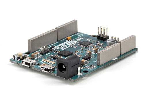
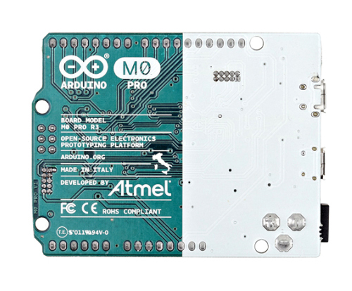
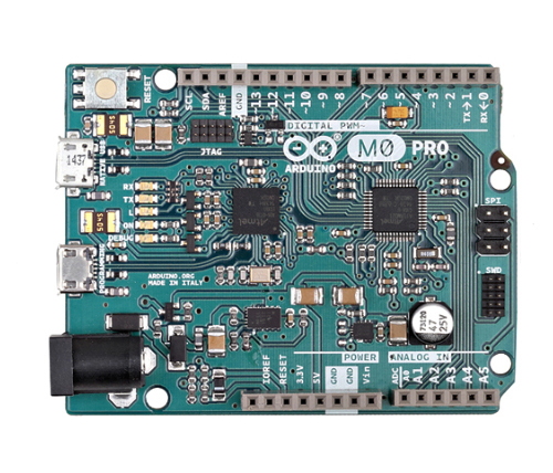
Arduino Zero Pro에서 Arduino M0 Pro로 이름이 변경되었습니다.Overview'아두이노 M0 프로'는 단순하지만 강력한, 아두이노 우노의 32비트 확장판 입니다. Atmel의 SAMD21 MCU를 사용하고, 32-bit ARM Cortex® M0 코어를 특징으로 합니다. M0 보드가 추가됨으로써, 아두이노는 향상된 성능을 제공하는 새로운 멤버 하나가 더 늘어나게 되었습니다. Atmel 코어는 한층 높아진 유연성을 제공하여 만들 수 있는 프로젝트의 범위를 넓혔고 때문에 M0보드는 32비트 어플리케이션 개발을 학습하는데 이상적인 교육용 도구가 될 것입니다. Atmel의 임베디드 디버거(EDBG)가 보드에 통합되어 있습니다. 이는 모든 디버그 인터페이스를 추가 하드웨어의 필요 없이 제공하기 때문에 디버깅을 더욱 쉽게 만들어 줍니다. 또한 EDBG는 가상 COM 포트를 지원하기 때문에, 장치 프로그래밍이 가능하며, 기존의 아두이노 부트로더 기능을 사용할 수 있게 해줍니다. Overview With the new Arduino M0 pro board, the more creative individual will have the potential to create one’s most imaginative and new ideas for IoT devices, wearable technologies, high tech automation, wild robotics and other not yet thinkable adventures in the world of makers. Summary
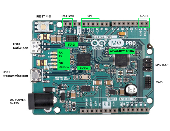
EDBG Microcontroller: AT32UC3A4256, 100pins VFBGA Operating Voltage: 3.3 V Input Voltage (recommended): 6-15 V Input Voltage (limits): 4.5-20 V Digital I/O Pins: 20, with 12 PWM and UART Analog Input Pins: 6, 12-bit ADC channels Analog Output Pins: 1, 10-bit DAC DC Current per I/O Pin: 7 mA Flash Memory: 256 KB SRAM: 32 KB Clock Speed: 48 MHz Schematic & Reference Design EAGLE files: arduino-M0-pro-reference-design.zip Schematic: arduino-M0-pro-schematic.pdf Power The Arduino M0 Pro can be powered via the micro USB connection or with an external power supply. The power source is selected automatically. External (non-USB) power can come either from an AC-to-DC adapter (wall-wart) or battery. The adapter can be connected to the board by plugging a 2.1mm center-positive plug into the board's power jack. Leads from a battery can be inserted in the Gnd and Vin pin headers of the POWER connector.
The board will automatically detect which power sources are available and choose which one to use according to the following priority: External power is required when the 500mA through the USB connector is not enough to power a connected USB device in a USB host application.
The power pins are as follows: Memory The ATSAMD21G18 has 256 KB of flash program memory (with 4 KB used for the bootloader). The bootloader is factory pre burnt by Atmel and is stored in a dedicated ROM memory. The bootloader is protected using the NVM fuse. Input and Output Each of the 14 digital i/o pins on the M0 Pro can be used as an input or output, using pinMode(), digitalWrite(), and digitalRead() functions. They operate at 3.3 volts. 7mA as maximum DC current for I/O pins and an internal pull-up resistor (disconnected by default) of 20-60 kOhms. In addition, some pins have specialized functions:
Communication
The Programming port is connected to EDBG, which provides a virtual COM port to software on a connected computer (To recognize the device, Windows machines will need a .inf file, but OSX and Linux machines will recognize the board as a COM port automatically.). The EDBG is also connected to the SAMD21 hardware UART. The Serial on pins RX0 and TX0 provides Serial-to-USB communication for programming the board through the ATSAMD21G18 microcontroller. The Arduino software includes a serial monitor allowing simple textual data to be sent to and from the board. The RX and TX LEDs on the board will flash when data is being transmitted via the ATSAMD21G18 chip and USB connection to the computer (but not for serial communication on pins 0 and 1). The Native USB port is connected to the SAMD21. It allows for serial (CDC) communication over USB. This provides a serial connection to the Serial Monitor or other applications on your computer. The SAMD21 also supports TWI and SPI communication. The Arduino software includes a Wire library to simplify use of the TWI bus. For SPI communication, you can use the SPI library.
If you use Linux-based OS follow the guide Arduino IDE on Linux-based OS. Uploading sketches to the SAMD21 is different from how it works with the AVR microcontrollers found in other Arduino boards: the flash memory needs to be erased before being re-programmed. Upload to the chip is managed by a dedicated ROM area on the SAMD21. Both the USB ports can be used to program the board. Programming port: To use this port, select "Arduino M0 Pro (Programming Port)" as your board in the Arduino IDE. Connect the M0 Pro programming port (the one closest to the DC power jack) to your computer. The programming port uses the EDBG as a USB-to-serial chip connected to the first UART of the SAMD21 (RX0 and TX0). The EDBG has two pins connected to the Reset and Erase pins of the SAMD21. Opening and closing the Programming port connected at 1200bps triggers a “hard erase” procedure of the SAMD21 chip, activating the Erase and Reset pins on the SAMD21 before communicating with the UART. This is the recommended port for programming the M0 Pro. It is more reliable than the "soft erase" that occurs on the Native port, and it should work even if the main MCU has crashed. Native port: To use this port, select "Arduino M0 Pro (Native USB Port)" as your board in the Arduino IDE. The Native USB port is connected directly to the SAMD21. Connect the M0 Pro Native USB port (the one closest to the reset button) to your computer. Opening and closing the Native port at 1200bps triggers a 'soft erase' procedure: the flash memory is erased and the board is restarted with the bootloader. Opening and closing the native port at a different baudrate will not reset the SAMD21.
RoHS CE |
|
|
상품의 사용후기를 적어주세요.
게시물이 없습니다


상품에 대해 궁금한 점을 해결해 드립니다.
게시물이 없습니다

고액결제의 경우 안전을 위해 카드사에서 확인전화를 드릴 수도 있습니다. 확인과정에서 도난 카드의 사용이나 타인 명의의 주문등
정상적인 주문이 아니라고 판단될 경우 임의로 주문을 보류 또는 취소할 수 있습니다.
무통장 입금은 상품 구매 대금은 PC뱅킹, 인터넷뱅킹, 텔레뱅킹 혹은 가까운 은행에서 직접 입금하시면 됩니다.
주문시 입력한 입금자명과 실제입금자의 성명이 반드시 일치하여야 하며, 7일 이내로 입금을 하셔야 하며 입금되지
않은 주문은 자동취소 됩니다.


법인명(상호) : 알제이(RJ)테크 대표자(성명) : 정제영 사업자 등록번호 안내 : [113-24-47248] 사업자정보확인
통신판매업 신고 2015-서울구로-0248 전화 : 070-8250-3303 팩스 : 02-6971-9251
주소 : 08206 서울특별시 구로구 신도림로 7 (신도림동) 금강리빙스텔 502호
개인정보관리책임자 : 정제영(rockjjy99@gmail.com) Contact rockjjy99@gmail.com for more information.

Copyright © 2017 오마이엔지니어. All rights reserved. Hosting by 심플렉스인터넷(주)